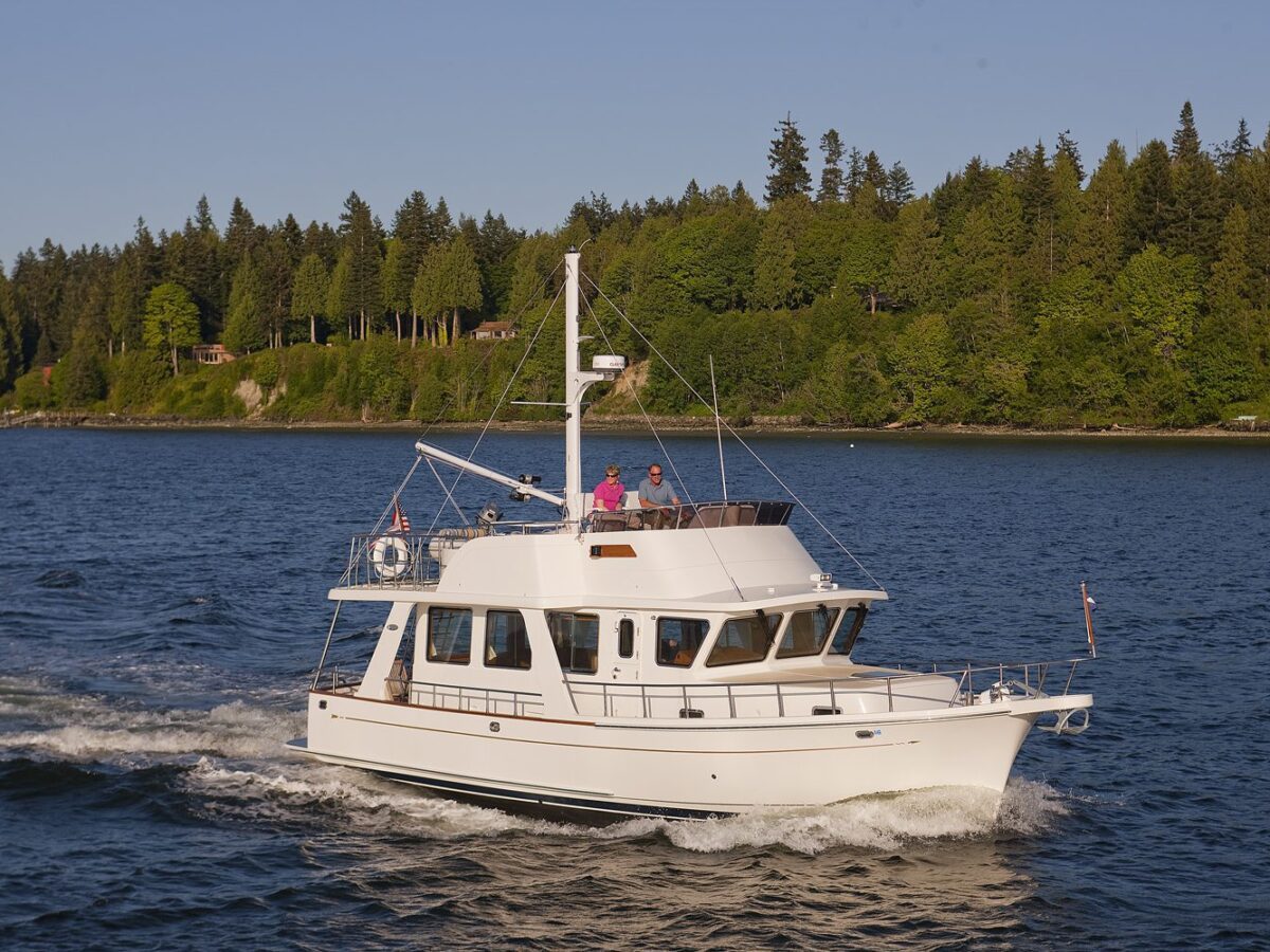
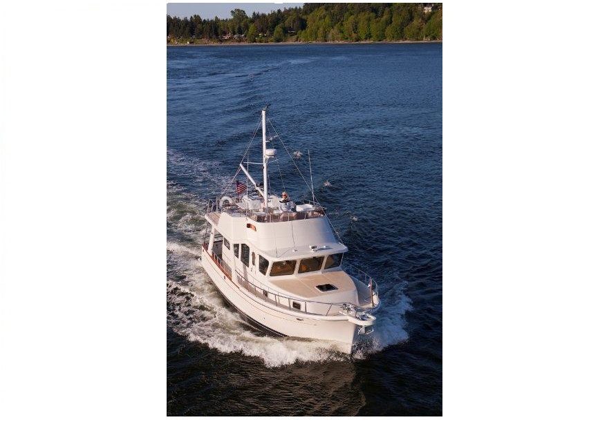
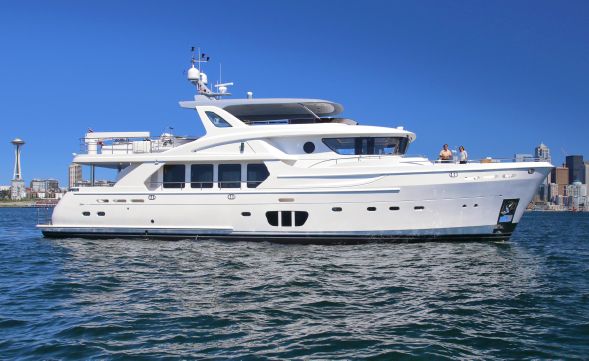
The Selene 92 “Ocean Explorer” is the result of an International collaboration of designers and architects under Howard Chen’s design team leadership. Working closely with renowned Dutch architect Guido De Groot and a group of International consultants we have developed a contemporary take on the long range yacht whilst capitalizing on builder Jet Tern Marines quality construction and reputation for experience and innovation in the displacement yacht sector.


Ask us a question and we will reply within 24 hours
Interested In This Boat?
General
| Year: | 2011 |
| Price: | NZD$0 |
| Additional Charges: | None |
| Boat Type: | Power |
| Hull Type: | Commercial |
| Location: | Auckland |
| Engine/Fuel: | Diesel |
| Hull Material: | GRP |
Dimensions
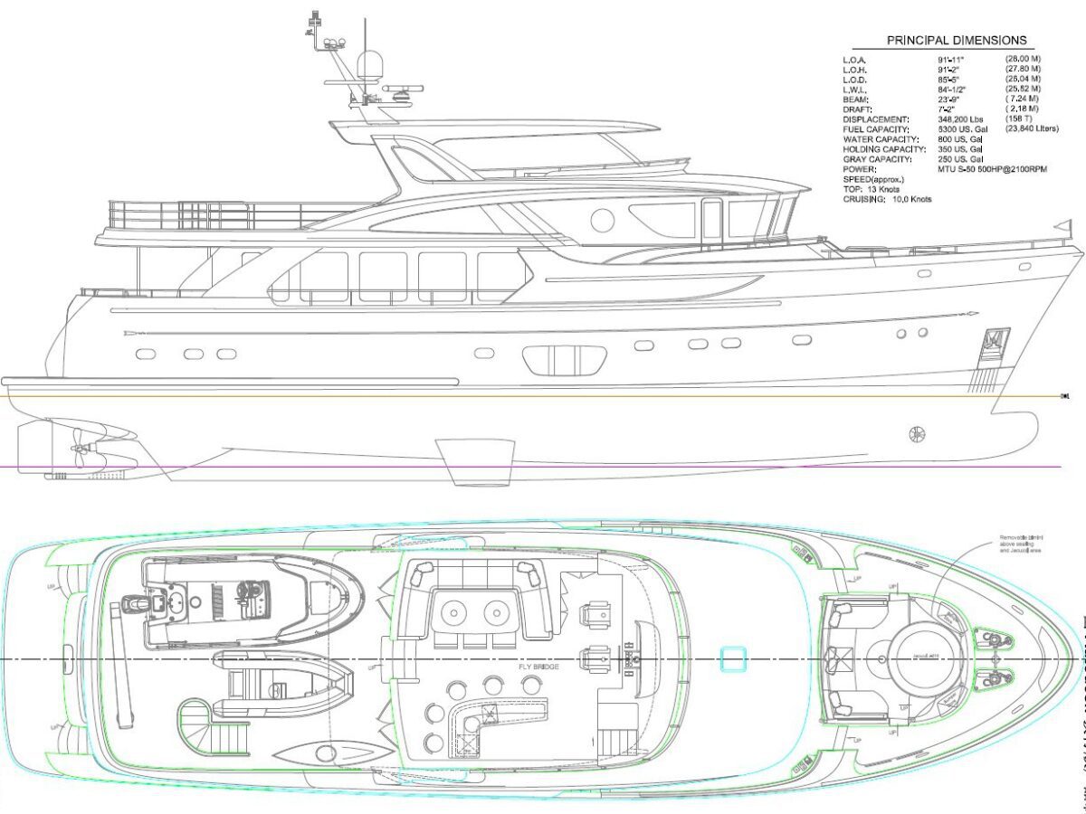
| Length: | 92 ft |
| LOA: | 27.06m |
| Beam: | 7.26m |
| Draft: | 2.08m |
| Displacement: | 308,560 lbs |
Engines
| No. of Engines: | 2 |
| Engine Brand: | Cummins |
| Engine(s) HP: | 610 |
| Cruising Speed: | 10 Knots |
| Max Speed: | 13 Knots |
Builder / Designer
| Builder: | Jet Tern Marine |
| Designer: | Howard Chen |
Tankage
| Fuel: | 18930 Litres |
| Water: | 3400 Litres |
| Holding: | Yes |
Construction
A Hull Lamination Schedule
- 1 Per construction plan, the area below waterline to use ‘Isophthalic’ Gelcoat and vinylester resin for the first 3 layers. Deck lamination schedule per construction plan. Construction plans pertaining to structure to be based on standards set by the RULES AND REGULATIONS FOR THE CLASSIFICATION OF SPECIAL SERVICE CRAFT (Lloyds)
B Gel-caoted fiberglass exterior
- 1 Hand laid fiberglass
- 2 Vacuum resin infusion hull and superstructure
- 3 4 watertight bulkheads
- 4 Transverse frames and longitudinal girders system
- 5 FRP radar arch with mast tree
- 6 FRP spiral staircase from cockpit to flybridge
- 7 Built in ‘U’ shape settee and table with storage under the foredeck
Construction
C Core Materials
- 1 Cabin side (veertical surfaces): Klegecell #R80 varying degress of thickness
- 2 Cabin top and deck (horizontal surfaces) Baltec or equivalent vertical end grain balsa, 1″ thick
- 3 Hull and superstructure to have ‘Coremat’ 2mm anti print thru material in first series of lamination before roving is applied
D Deck/Hull joint
- 1 Between deck and hull flange: 3M 5200
- 2 Inside of joint: 3 layers of M. & W.R. in all accessible locations
- 3 Mechanical fastening: 3/8″ thru bolts on 6″ centers
E Longitudinal Stringer
- 1 Hull: FUll length each port and starboard
- 2 Hull Tranverse frame system
F Water tight bulkheads:
- Per construction drawing to include, but not limited to the following areas: Between Lazarette and crew quarters , crew quarters and E/R, E/R and lower guest cabins, Aft bulkhead of Fwd. Guest cabin, and chain locker/collision bulkhead. “Roxtec” thru bulkhead fittings used to maintain watertight seal
Engine
A Port Main Engine:
- 1 Detroit Diesel/MTU Series 60, 600HP @ 2100 RPM, Wet exhaust & 24VDC starting
- 2 Gear Box: TwinDisc MG-5114DC, w/3.28:1 reduction
- 3 Engine Instrument Panel: Three (3) instrument panels with alarm that will monitor Tachometer, Engine oil pressure, Engine water temp, System voltage, Gear oil pressure and fuel burn.
- 4 Alternators: 24VDC
- 5 Engine Controls: Five (5) stations: pilothouse, fly bridge, aft deck and, P&S bridge and engine room(option).
- 6 Walker “Air Sep” crankcase ventilation
- 7 Two (2) 4D batteries connected in series for 24VDC start
- 8 Engine beds to have 1/2” stainless steel cap on top of bed and 1/4″ plate on sides, plates are to be highly polished stainless steel.
- 9 Each engine mounted on (4) resilient mounts
Engine
B Starboard Main Engine:
- 1 Detroit Diesel/MTU Series 60, 600HP @ 2100 RPM, Wet exhaust & 24VDC starting
- 2 Gear Box: TwinDisc MG-5114DC, w/3.28:1 reduction
- 3 Engine Instrument Panel: Three (3) instrument panels with alarm that will monitor Tachometer, Engine oil pressure, Engine water temp, System voltage, Gear oil pressure and fuel burn.
- 4 Alternators: 24VDC
- 5 Engine Controls: Five (5) stations: pilothouse, fly bridge, aft deck and, P&S bridge and engine room(option).
- 6 Walker “Air Sep” crankcase ventilation
- 7 Two (2) 4D batteries connected in series for 24VDC start
- 8 Engine beds to have 1/2” stainless steel cap on top of bed and 1/4″ plate on sides, plates are to be highly polished stainless steel.
- 9 Each engine mounted on (4) resilient mounts
Engine
C Propellers:
- 1 43″ x XX”, 5 blade NiAl Bronzel alloy counter rotating propellers. Propellers to be built to I.S.O. class 1
D Propeller Shafts:
- 1 Aqualloy 22 or equivalent, 3-1/2″ diameter
- 2 Taper details: Standard SAE
- 3 Line cutters on each main engine shaft
Engine
- E Stern tubes:
- 1 Amartech Shaft System
- 2 Amartech AxiSeal Shaft Seal
- F Fuel Filter:
- 1 Two (2) Racor 75-900MAX duplex filters w/30 micron elements in addition to secondary engine mounted filter for each engine
Engine
F Noise Control Systems:
- 1 Hull Damping – Area above the propeller rotation plane to be treated with two (2) layers of E-A-R Specialty Composites Isodamp CN Tiles (CN-62), alternating between resin and chopped glass to form a constrained layer damping system to be the inboard side of the shell plate.
- 2 Engine room ceiling, fwd and aft bulkheads treated with 2″ of Soundown lead foam and 1.75″ of acoustic insulation. Inboard tank sides, underside of deck, forward side of engine room bulkhead and ventilation ducts to be treated with 2″ of Soundown lead foam and 1.75″ of acoustic insulation and covered with white aluminum perforated panels by Soundown.
- 3 Salon/galley cabin sole to have 45mm honeycomb core system, and 1/4″ Soundown Tuff-Mass “decoupler” layer.
Engine
F Noise Control Systems
- 4 Engine room hatches to have rubber gasket and lock down mechanism
- 5 Two S/S supports for salon cabin sole filled with lead shot for vibration absorption and mounted on Soundown rubber mounts
- 6 Soundown Quiet Pro lining covering engine room intake ventilating ducts, 1” thick secured with epoxy and mechanical fasteners
- 7 Insulated bulkheads in living areas with acoustic insulation per drawing
- 8 Forward accommodation areas between hull and hull ceiling to be insulated with acoustic insulation.
- 9 Salon overhead between deck underside and Majilite overhead panels is to be treated with 1″ thick acoustic insulation
Engine
G Exhaust System:
- 1 Underwater wet exhaust system for each engine design and supplied by Marine Exhaust Systems, Florida
H Generator #1:
- 1 Onan model #40MDDCF 40KW/50kVA 220/380VAC 3-phase/50Hz
- 2 Wet exhaust system using gen-sep water separator
- 3 24VDC start
- 4 Alternator: 20 amp
- 5 Main panel located in pilot house and start stop on main electrical panel
- 6 Racor 500MA filter with bypass
Engine
I Generator #2:
- 1 Onan model #22.5MDKBT 22.5KW/28.1kVA 220/380VAC 3-phase/50Hz
- 2 Wet exhaust system using gen-sep water separator
- 3 24VDC start
- 4 Alternator: 20 amp
- 5 Main panel located in pilot house and start stop on main electrical panel
- 6 Racor 500MA filter with bypass
Engine
J Hydraulic System:
- 1 ABT Hydraulic powered 50HP bow and stern thrusters using 16″ tunnels with proportional controls at 5 stations
- 2 ABT TRAC #370 digital stabilizer system with 20 sq. ft. fins and dual station control. Stainless steel kelp cutters fwd. of fins tied to bonding system. System to be powered with engine driven pump.
Engine
J Hydraulic System
- 3 Hydraulic bilge pump 180gpm, plumbed to all watertight areas with 2″ PVC, schedule 80 pipe to a manifold in the engine room.
- 4 Hydraulic anchor wash pump/fire fighting pump 180gpm
- 5 Each main engine fitted with a clutchable PTO and hydraulic pump
Engine
HEATING, VENTILATION AND AIR CONDITIONING SYSTEMS (HVAC)
A Air Conditioning System:
- Tempered Water System:
- 1 Dometic CRUISAIR Tempered Water System (chilled water) 12 tons, 400VAC 3-phase
- 2 Modular Tempered Unit: (x3) Chiller3, 4 tons, 3-stage, 400VAC, 3-phase (MTD48ECK)
- 3 Variable Frequency Drive: (x3) VFD 380V 14.3A 50Hz, (763300016)
- 4 Control Panel: Unit Panel , 2 Pump Relays, 400/230VAC, 3-phase
- Air Handlers:
- 5 Crew Cabins – (2) AT6-DCZ-FC-1KW, 230VAC
- 6 Crew Mess – AT9DCZ-FC-1.5KW, 230VAC
- 7 Master Cabin and Head – (2) AT18-DCZ-FC-3KW, 230VAC
- 8 Port Guest Cabin and Head – AT9DCZ-FC-1.5KW, 230VAC
- 9 Starboard Guest Cabin and Head – AT9DCZ-FC-1.5KW, 230VAC
- 10 VIP Cabin and Head – AT18-DCZ-FC-3KW, 230VAC
- 11 Pilothouse – (2) AT18-DCZ-FC, 230VAC
- 12 Galley – AT18-DCZ-FC, 230VAC
- 13 Salon/Dining – (2) AT24-DCZ-FC, 230VAC
- 14 Engine Room – ATL36DC, 230VAC
- 15 Circulation Pump: CPOD180B3X
- 16 Sea Water Pump: PS3000B3X
Room Controllers:
- 17 (11) SMX LCD Key Pad/Display, Grey
Engine
HEATING, VENTILATION AND AIR CONDITIONING SYSTEMS (HVAC)
Accessories:
- 18 Expansion Tank-TW-Bladder
- 19 Balancing Flow Control
- 20 Automatic Vent
- 21 Backflow Preventer Valve
- 22 Pressure Regulator Valve
- 23 Vent Dual Spiro 2″ FPT
- 24 Strainer
B ENGINE ROOM VENTILATION SYSTEM:
- 1 One (1) Intake Fan – One louvered vent Starboard side deck aft in the engine room with screened blower inlet. The intake fan will pull through a Livos Technology moisture eliminator located at the deck side.
- 2 One (1) Exhaust Fan – One louvered vent on Port side decks aft in the engine room with screened blower inlet.
- 3 Fire/Smoke Dampers – Stainless Steel Rear Flanged dampers equipped with a side mounted Honeywell H-2024 Fast-Acting, Two Position Actuator. One damper (1) each installed on the engine room side of each blower for easy access. Each damper will be normally open and will close on SEAFIRE actuation.
- 4 (1) intake fan and (1) exhaust fan have adjustable speed controls.
- 5 Automatic Blower control and Damper Closure on SEAFIRE Actuation (See Fire Protection System)
C HEADS:
- 1 One (1) Exhaust Blower each head
- 2 One (1) on/off switch and internal timer
- 3 Ducting is to be 4″
D STATEROOMS:
- 1 One (1) Supply Blower for crew, master, and lower staterooms.
- 2 Blower located to insure minimal noise in stateroom
- 3 Ducting is to be 4″
- 4 Cabin intake air is to come from a louvered intake vents located outside the boat and ducted to the stateroom.
Engine
5 FIRE SUPPRESSION SYSTEM
- A SEAFIRE Fixed Fire extinguishing system based on FM200 agent, automatic and manual, with electronic shutdown of engines, generator(s) and ventilation system in the Engine Room.
- 1 (1) model #130054 240 lb. (106 Liter) FM-200 cylinder assembly 2″ valve.
- 2 (1) model #124173 Cylinder supervisory switch Normally Open
- 3 (1) model #122305 Outlet adapter 2″ valve
- 4 (2) model #130046 Marine Cylinder Mounting Bracket 16″
- 5 (1) model #131050 Pneumatic control head
- 6 (1) model #121-121 Actuation hose (pilot hose) 48″
- 7 (2) model #121105 Fitting 1/4″ Straight
- 8 (1) model #134020 Manual pull station yacht type 20 foot
- 9 (1) model #131-261 Engine Shutdown & Restart 8 Circuit 24 V
- 10 (2) model #131082 Nozzle 1″
- 11 (2) model #131020 Pneumatic heat detector, Marine
- 12 (1) model #131023 Pneumatic detection, tubing 3/16″ copper 30 foot
- 13 (2) model #121096 Fitting 3/16 Union
- 14 (6) model #121097 Fitting 3/16 Nut
- 15 (1) model #121098 Fitting 3/16 Tee
Engine
5 FIRE SUPPRESSION SYSTEM
- 16 (1) model #131010 Pressure switch single pole double throw
- 17 (1) model #123172 UV Protected Plastic Sign, “Warning”
- 18 (1) model #123-173 UV Protected Plastic Sign, “FM200”
- 19 (1) model #123174 UV Protected Plastic Sign, “Remote Pull Station”
- 20 (1) model #123175 UV Protected Plastic Sign, “Local Operation”
- 21 (1) model #131296 Visual audible alarm (Horn/Strobe)
- 22 (1) model #123144 Design Manual, FM-200 Marine
- 23 (1) model #123145 FM-200 Marine OWNERS MANUAL
- 24 (1) model #131100 FM 200 Agent Factory Fill
- 25 (1) model #131040 Manual pull station yacht type 40 foot
- 26 (1) model #131062 Dual discharge adapter
- 27 (1) model #131-290 deluxe discharge alarm
B Portable Fire Extinguishers:
- 1 Pilothouse, Fly Bridge, Galley, Salon, and Master Stateroom: One (1) each USCG TYPE B-II (six total).
- 2 Guest and Crew Cabins: One (1) each USCG TYPE B-1 (Five Total)
Engine
6 STEERING SYSTEM
- A Hydraulic Steering System:
- 1 Kobelt Hydraulic Steering System – 35 degree Rudder Deflection, Single Station (pilothouse)
- 2 Helm Pump: Variable Displacement, Long Shaft, #7005-AL
- 3 Cylinders: Two(2) x Model #7080-B16 balanced cylinders with 3.0″ Bore with 16″ Stroke.
- 4 Power Follow-up servo valve #7148-DC24
- 5 Safety and Bypass Valve: #7020
- 6 Double arm for 7080 cylinder: Model #7084-T
- 7 Single Arm Tiller Arm: Model #7084-S
- 8 Two (2) rod ends Model #7080-0004
- 9 Tie bar ends with nut (2) Model #7080-1004
- 10 Header Tank: Model #7002-A
- 11 Rudder feedback unit Model #7174-B
- 12 Master rudder angle indicator Model #7175-MY
- 13 Rudder angle indicator Model #7175-SY
- 14 Transfer box : 1 station +AP Model #7173-TX2
- 15 Jog lever for Five(5) stations Model #7170-A2
- 17 Single solenoid valve base Model #7144
- 18 Solenoids 7148-SOL24, 24VDC
- 19 Power pack is (2) Eaton 70122-LH, 7/8-13 tooth 2 bolt SAE “B” pad, pressure compensated pumps including reservoir, tank top return filter, low level/high temperature switch and pressure gauge. Cooling of hydraulic oil is done through one heat exchanger that are fed with raw water from a gear driven pump on each main engine.
- 20 Flow control model #3005
- 21 Non drain back valve #7143
Engine
6 STEERING SYSTEM
- B Hydraulic lines:
- 1 Seamless stainless steel tubing 1″ I.D. with reinforced rubber hydraulic lines to the hydraulic cylinders.
- C Steering wheel:
- 1 Stainless steel destroyer type in pilothouse
- 7 RUDDERS
- A Rudder stock:
- 1 3 1/2″ 316 Stainles Steel
- B Rudder:
- 1 316 Stainless Steel and FRP to NACA 0015
- C Rudder carrier shoes:
- 1 Two piece fabricated 316 stainless steel. Main piece fastened to hull by rivets. Aft piece removable so that rudders can be removed.
- D Rudder stock stuffing box:
- 1 Bronze traditional style x 2
- E Rudder stock tube:
- 1 FRP with bronze/rubber cutlass bearing at the bottom
- 2 “T” bolt clams at stuffing box x 2
Plumbing System
8 TANKAGE AND PLUMBING SYSTEM
A Water Tanks:
- 1 Number and capacity: Two (2) tanks totaling 900 gallons
- 2 Material: Fiberglass from male molds with FDA approved gel coated interior
- 3 Inspection plates: Appropriately positioned and sized for access
- 4 Tanks air tested to 4.5 pounds per sq. inch
- 5 Each tank to have “WEMA” level gauge
- 6 Each tank to be fitted with sight gauge
- 7 Tank baffles to be spaced on 24″ centers
- 8 Exterior of tanks finished in gel coat
- 9 Tanks to comply with class standards for potable water systems for use on boats
- 10 Cleanliness: Tank interior surfaces to be thoroughly vacuumed and wiped down prior to final closure
B Fuel Tanks:
- 1 Number and capacity: Three (3) main tanks and one day tank (400 gallons) totaling approximately 6200 gallons. One forward tank will be transferred to main E/R tanks thru the fuel transfer system.
- 2 FRP construction from male molds using Vinylester resin. To comply with all class standards for diesel fuel tanks. Tanks to be coated with fire retardant Gelcoat on outside to comply with the class standard for fire resistance.
- 3 Inspection Plates appropriately positioned for interior access by average size man. Plates to be fitted with labels that contain all manufacture information. Each internal baffle to have a removable panel to allow access to entire interior of all fuel tanks.
- 4 Each tank supplied with tank gauges with displays located at the helm station
- 5 Magnetic sight gauge for each E/R fuel tank (Type Approved)
- 6 Each tank to be air tested to 4.5 pounds per sq. inch or as required by Standard
- 7 Provide baffles on 24″ centers
- 8 Orberdorfer gear pump (5 GPM) or equivalent fuel pump with timer switch and Racor 731000MA dual fuel filters with 10 micron element which can transfer fuel from tank to tank and provide fuel polishing.
- 9 Orberdorfer high speed gear pump (30 GPM) for transfering fuel between the three main supply tanks.
- 10 Exterior of tanks finished in gel coat
- 11 Cleanliness: tank interior surfaces to be Vacuumed and wiped clean before final closure
- 12 Each tank to have one (1) 1-1/2” ID vent lines
- 13 Each tank to have separate 2” I.D. fill pipe located a minimum distance of 18” from any ventilation openings.
- 14 All hardware that comes in contact with fuel to be bonded into the ships grounding system.
C Fuel Pipe, Fittings and Hose:
- 1 Supply lines from engine room and forward tanks are Stainless Steel, Grade 304L, SCH 40 Electric Resistance Welded 1-1/2” ID.
- 2 Fuel line to main engine filter and return is ¾” ID Stainless Steel Tubing, Grade 304L, SCH 40, Parker brand fuel hose connections and swaged fittings
- 3 Fuel lines to the generator and return to be ½” ID Stainless Steel Tubing, Grade 304L, SCH 40, Parker brand fuel hose connections and swaged fittings
- 4 Fuel Transfer lines to be Stainless Steel, Grade 304L, SCH 40 Electric Resistance Welded 1-1/2” ID.
- 5 Fuel Fill lines to be Stainless Steel, Grade 304L, SCH 40 Electric Resistance Welded 2” ID.
- 6 Vent lines to be Stainless Steel, Grade 304L, SCH 40 Electric Resistance Welded 1-1/2” ID.
D Water Piping:
- 1 Cold water: Hose from water tanks to water pump and to accumulator to be 1″ diameter reinforced and approved for potable water; Branch lines to be 1/2″ PVC pipe (blue) PEX or equivalent
- 2 Hot water: Reinforced 1/2″ PVC pipe (red) PEX or equivalent
- 3 Sea water hoses: Trident brand reinforced for marine use and provided with double stainless steel clamps below the water line
- 4 All hoses used shall meet the requirements for service as set out by the class standards for the system intended.
E Hot Water Heater System:
- 1 Heater: Two (2) 50 gallon with dual 240VAC elements
- 2 System to have a recirculation pump
F Thru Hulls:
- 1 Bronze body, S/S Balls and Teflon seats
- 2 Grounding wire: #6 gauge green wire
- 3 Each thru hull to have a clearly visible tag indicating use
- 4 Each thru hull to be readily accessible
G Fresh Water System:
- 1 Main Pump: Headhunter Mach 5, AC pumps with pressure regulator and Groco WSA-1000 strainer on pump inlet
- 2 5 gallon accumulator tank with pressure gauge
- 3 Hose from water tanks to water pumps and to accumulator to be 1″ diameter reinforced and approved for potable water
- 4 Back up Pump: Headhunter Mach 5 with pressure regulator and Groco WSA-1000 strainer on pump inlet installed as back up to main pump
- 5 Filter: Water filter housing with a 5 micron sediment filter installed downstream of fresh water discharge manifold
- 6 Pump Selection Manifolds (2): Pump inlet and discharge manifolds made of stainless steel standard pipe. Supply manifold furnished with isolation ball valves from each fresh water tank, to each fresh water pump, and from the water maker. Discharge manifold furnished with
- isolation valves from each pump.
- 7 Fresh water fill w/SS cap
- 8 Fresh water system will use rigid PVC piping and PEX tubing
- 9 Water maker: 2000GPD Village Marine with UV sterilizer, media filter and remote panel.
Plumbing System
8 TANKAGE AND PLUMBING SYSTEM
H Plumbing fixtures:
- 1 Head sinks – eight (8) total: Master Cabin x 2, salon day head , VIP/guest lowers x 3, and aft crew.
- 2 Galley sink: Double S/S
- 3 Head faucets: Grohe Model# 33170-0000 chrome
- 4 Galley, Grohe Model# 33939 chrome/black
- 5 Shower fixtures: All Grohe #28.049 handle, #28786 soap dish, #28.820 24″ shower bar, #28.151 hose, #34.436 thermostat valve
- 6 “Scandvik” aft deck shower installed at the stern+E353
- 7 Fresh water outlets on the foredeck, aft deck, fly bridge, bridge deck and one (1) in engine room
I Shower and sink sump pump system for crew head:
- 1 One (1) Lancaster sump-less sump pump #399 or equivalent located under cabin sole in laundry area. Shower ,sink, e/r sink and washer drain to pump via PVC manifold with 1 1/2″ outlet. Sump pump discharges to gray water tank. Requires 1/2 vent line.
J Sump pump system for forward guest heads:
- 1 One (1) Lancaster sump-less sump pump #399 or equivalent located under cabin sole in laundry area. Shower, sink, e/r sink and washer drain to pump via PVC manifold with 1 1/2″ outlet. Sump pump discharges to gray water tank. Requires 1/2 vent line.
K Bilge Pumps:
- 1 Electric: Six(6) Diaphragm pumps or equivalent, 1″ diameter ports, with “Ultra Senior” auto float switch #UPS-01-24/32.
- 2 Manual: Edson Model #117AL-200-230-PC or equivalent
- 3 Hydraulic driven emergency pump: (1) Pacer hydraulic pump or equivalent plumbed to all water tight compartments with 2″ PVC piping. Manifold for emergency pump to be located in easily accessible location.
- 4 Electric driven emergency bilge pump: (1) Pacer model #ISP2GL D3.0C or equivalent plumbed to the emergency bilge manifold for use as a back up if the hydraulic driven emergency pump fails.
- 5 High Water Bilge Alarm Panel – High water bilge sense will come from std. Ultra Senior in each bilge compartment. Visual and audio alarm panel in pilot house.
- 6 All bilge piping to meet class standards.
L Toilets and Holding Tank System:
- 1 All toilets to be TECMA fresh water toilets
- 2 Water supply to toilets to be fresh water only
- 3 Holding Tank: One (1) FRP 250 gallon holding tank
- 4 Piping to use only schedule 80 PVC pipe or Trident “Odor Shield” #140 sanitation hose
- 5 Holding tank overboard pumps: Edson “Bone Dry” #120ELB electric and Edson “Bone Dry” manual pump or equivalent
- 6 Holding tank vent to use vent filter
- 7 Deck fitting for portable evacuation facility
- 8 Fast Systems L-X2 Modular Marine Sanitation System
M Gray Water System:
- 1 Tank: One (1) FRP 150 gallon tank. All sinks, showers, and air conditioning condensate to drain to tank. All drains to have “P” traps and sloped down hill run to tank. Exception: Crew head sink and shower, laundry and forward guest cabin head drains will be pumped to gray water tank with the “Lancaster” sump-less sump pumps as described. Tank equipped with electric and manual discharge pumps, level switch for pump starting, and level monitor system.
- 2 Tank overboard pumps: Edson “Bone Dry” #120ELB electric and Edson “Bone Dry” manual pump or equivalent
- 3 Manual back up pump: Edson Model #117AL-200-230-PC or equivalent
N Sea Chest for raw water supply to various systems:
- 1 Main Engines, Generator(s), water maker intake, air conditioning and spares.
- 2 Dual 6″ diameter intakes port and starboard of keel using two strainer assemblies with Monel baskets.
- 3 All raw water piping to meet class standards.
O Oil Change System:
- 1 AC powered oil change system plumbed to each engine and the two main engine gearboxes.
- 2 All hose used in oil change system to be Parker brand fuel hose and swaged brass fittings
P Anchor Wash/Fire Fighting Pump:
- 1 Hydraulic drive anchor wash/fire fighting pump: One (1) Pacer hydraulic pump or equivalent – 2″ intake thru-hull and Groco strainer at bow. Provided “y” valve to switch from anchor wash to fire fighting system. Fire fighting to consist of a “Izerwaren” valve #91.778 , Nozzle #91.718, (2) 91.707 fire hoses with couplings, stowed in #91.727 container .
Q Central Vacuum system:
- 1 Serenity plus power team wand kit
- 2 Inlet valves – plastic inlet valves with wires in brown
- 3 Hose sock-gray
- 4 Floor rug combo tool
Plumbing System
9 ELECTRICAL SYSTEM
A The AC electrical system:
- 1 The AC electrical system is a three phase 230/400VAC distribution system with a maximum capacity of 60kW. Power is supplied from two Onan generators and through one 100 amp shore power connection. The vessel is fitted with a 35kVA shore power converter allowing connection to any shore connection worldwide. Provisions have been made for the seamless transfer of power from generator to generator, or generator to shore side power connection.
- 2 Atlas or ASEA 35kVA shore power converter with seamless transfer from generator to shore power. Glendenning shore power retractor for shore power connection at the stern and 20 meters cable for shore power supply.
- 3 230VAC, 3.0kVA inverter system for emergency power, control power to the helm station and for refrigeration during times when the generators are offline.
- 4 AC Outlets are standard English format 230VAC. Locations TDB
- 5 All outlets in head compartments, mechanical spaces, exterior and galley are GFCI type. All external outlets have water proof covers.
- 6 One (1) Glendinning shore power cord retrieval system provided for the 200-500VAC, 100 amp. ships shore power connection. The system to be provided with 100′ of shore power cable. Shore power inlet to be located at the stern of the vessel.
B The DC electrical system:
- 1 The DC electrical system is a 24VDC distribution system with a maximum capacity of 600 amp/hours. The DC system is to provide limited power the ships inverter system and provide power to the helm station DC equipment.
- 2 Standard batteries are located per machinery layout drawing
- 3 24 VDC house battery bank – Consists of 12, 2 volt AGM batteries @ 600 A/H each. connected in series. A total battery bank capacity of 600 amp/hours is provided for emergency, control, ships equipment and limited operation without operation of a generator or shore power
- connection.
- 4 12 VDC helm power is drawn from one 200 A/H battery and a 24 to 12VDC converter system to maintain the battery
- 5 Port main engine starting – (2) AGM batteries connected in series for 24VDC starting. Switching logic to parallel with 24VDC house bank for emergency starting.
- 6 Starboard main engine starting – 2 AGM batteries connected in series for 24VDC starting. Switching logic to parallel with 24VDC house bank for emergency starting.
- 7 #1 Generator starting- (2) – Group 31 AGM batteries connected in series for 24VDC starting. Switching logic to parallel with 24VDC house bank for emergency starting.
- 8 #2 Generator starting- (2) – Group 31 AGM batteries connected in series for 24VDC starting. Switching logic to parallel with 24VDC house bank for emergency starting.
Plumbing System
9 ELECTRICAL SYSTEM
C 24VDC battery charging:
- 1 One 24VDC, 100amp battery charger
- 2 Inverter/charger provides a total of 70 amps at 24VDC for the house battery bank
- 3 Main engine starting battery bank is charged from the respective engine alternator
- 4 Generator starting battery bank is charged from the respective engine alternator
- 5 Each charging source can be switched to accommodate any single failure of a charging device.
D Vessel Monitoring:
- 1 Maretron backbone to be run the length of the vessel for vessel monitoring equipment installation (NMEA 2000)
E Wire:
- 1 All wire to be marine grade, tinned conductor, 600 volt insulation type and sized according to the Class Standards.
F Wire Labeling:
- 1 When possible wiring to be color coded per the class standards
G Wire Terminations:
- 1 Connectors to be ring type with closed end seamless construction.
H Corrosion control:
- 1 All thru hulls to be bonded together with a #6 (13MM^2) green wire and tied into the DC negative system
- 2 All hardware mounted below water line – i.e. stuffing box, rudder shoe, rudder frame, all thru hulls, engines, and strainers to be connected to bonding system
- 3 Zinc plates to be tied into the bonding system based on the hull potential requirements of the vessel.
I Electrical Panels:
- 1 Main AC distribution and control panel located in E/R, sub panels located fore and aft on each deck as required
- 2 Main DC distribution and control panel located in E/R, sub panels located fore and aft on each deck as required
- 3 AC/DC distribution panel in pilothouse for helm instrumentation and equipment
- 4 House battery control at the helm station
- 5 Engine/gen start battery and emergency parallel control panel at entrance to engine room, control of the panel at the helm station
- 6 Generator start/stop panel in pilothouse
- 7 Helm station control and monitoring panel for bilge pumps, engine room ventilation, navigation lights, high water alarms, pump monitoring and other shipboard systems.
Interior
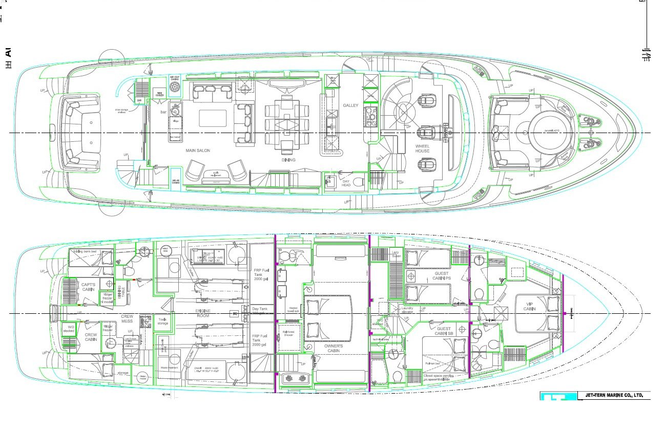
10 INTERIOR:
A General:
- 1 Teak, cherry or oak veneer ( straight grain or mountain grain )
- 2 Bulkheads, teak or cherry veneer
- 3 Formica finished ceiling & bulkhead for bathroom
- 4 Drapery or blinds for saloon & each stateroom
- 5 Grab rails, teak
- 6 Headlining, acoustical vinyl
- 7 Push button for all door lockers & drawers
- 8 Carpet, teak & holly or wood parquet interior floor for cabins
- 9 Metal non-skid flooring for engine room
- 10 Floating floor
- 11 Tinted tempered window glass 10~12 mm
- 12 Clear tempered glass 12mm for front windshield
- 13 Corian or granite head floor
- 14 Granite galley counter top w/back splash
- 15 Granite head counter top w/back splash
- 16 Interior steps to all teak. Corner of steps to have nonskid varnish.
- 17 Interior lockers and drawers to be locking with chrome push button
- 18 Interior overhead panels – Removable, held in place by Velcro.
- 19 Interior door lock sets to be chrome brass
- 20 Interior cabin doors to have rubber gaskets for sound reduction and door hooks
- 21 Hanging lockers to have automatic interior lights controlled by micro switch. Lined with Cedar.
- 22 Solid (non louvered) cored doors for heads and staterooms 1.25″ thick with rubber gaskets on door jambs
- 23 Interior teak woodwork including cabin sole in pilot house to be varnished with 60% gloss varnish
- 24 Salon tables, pilothouse table to be varnished with high gloss varnish
- 25 All hand rails to be teak.
- 25 Structural bulkheads dividing staterooms and heads to have ¾” furring strips on each side to allow application of ¾” thick sound insulation. The finished bulkhead material of 3/8” thickness to be applied over this.
- 26 Mirrors are located thru out vessel as shown on interior drawings
- 27 All drawers to have stainless steel ball bearing slides
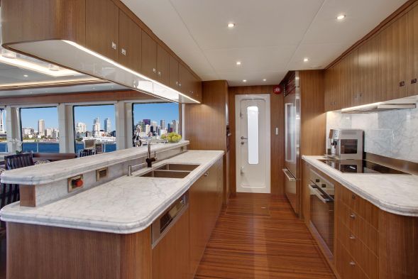
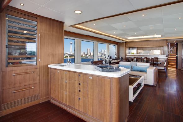
B Galley
- 1 Subzero or Liebheer home size large refrigerator
- 2 Ice maker
- 3 Microwave
- 4 Electric or propane stove
- 5 Dishwasher
- 6 Trash compactor
- 7 Exhaust fan
- 8 Counter top w/integral bar
- 9 S/S double sink
- 10 Single lever swivel type retractable faucet
- 11 Overhead cabinets
- 12 Drawers & storage lockers w/shelves under counter
- 13 Pantry to starboard of galley
- 14 Sliding doors to galley to have frosted glass panels
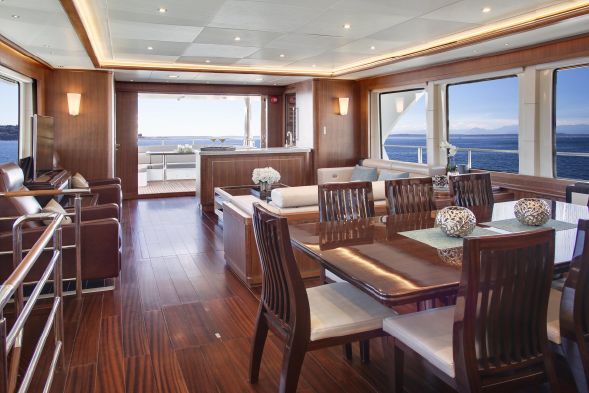
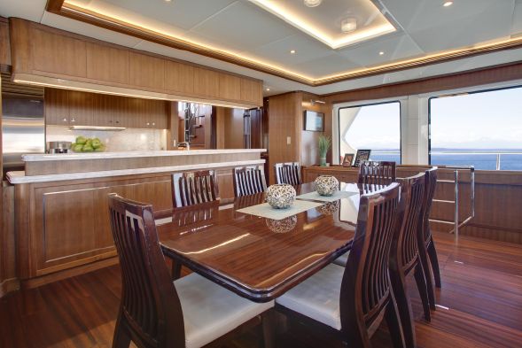
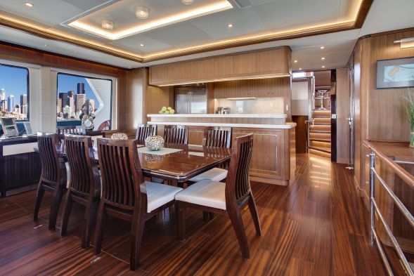
C Dining room:
- 1 Leaf style dining table seats for 8 persons
- 2 Loose chairs-8
- 3 Cabinet storage below windows port & starboard
- 4 Wood/mirror overhead lighting over the dining table area
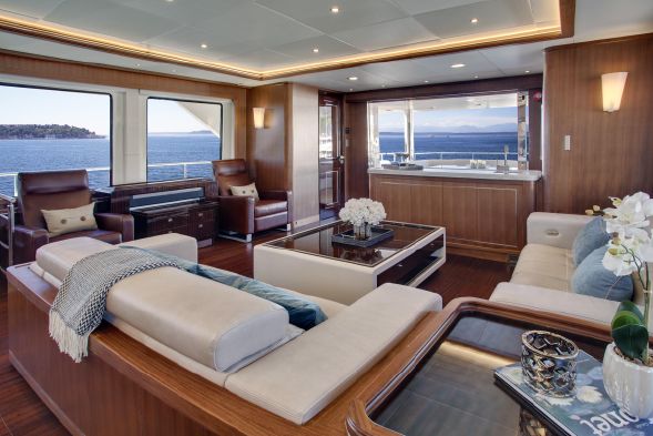
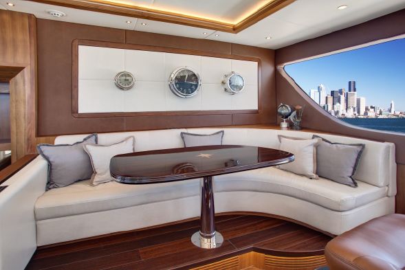
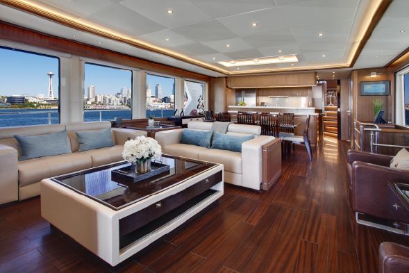
D Main Salon:
- 1 Floors: Carpet with 2 lb.,/sq. ft. 1/2 thick Soundown underlayment pad
- 2 Sofa with hi-lo foldable teak parquet table
- 3 Countertop & corner table
- 4 Entertainment center w/pop-up TV cabinet
- 5 S/S sliding door for saloon entrance
- 6 OceanAir blinds w/drapes
- 7 TV lift for 50″ plasma TV on side of salon (TV not included)
- 8 Prewire for surround sound speakers
- 9 Teak valance/air con soffit P&S and aft sides of salon
- 10 Two overhead teak hand rails
- 11 Mullions along port and starboard side for installation of window treatments
- 12 Overhead to have perimeter recess with strip lighting
E Day Head:
- 1 Floors: Teak
- 2 Counter top: Granite with bull nosed edge
- 3 Mirror and towel bar as shown on drawing
- 4 Cabinet/joiner work: All teak
- 5 Locker and drawer interior finish: Formica
- 6 Toilet paper holder and Towel bar:
F Master Cabin:
- 1 Floors: Carpet with 2 lb./sq. ft. 1/2″ thick Soundown under lament pad
- 2 Cabinet/paneling: Varnished teak
- 3 Mattress: Standard Queen size
- 4 Hanging lockers to be cedar lined with full length mirrors on inside of doors
- 5 Side cabinets & drawer bureaus
- 6 Full high wardrobe & dressing room with automatic light & aromatic cedar liner.
- 7 Safe located at master stateroom
- 8 Sofa at starboard master cabin
- 9 TV/Video cabinet
- 10 Vanity bureau with stool
- 11 Teak headboard frame
Interior
10 INTERIOR:
G Master Stateroom En-suit:
- 1 Floors: Ceramic or stone tile to be specified with order
- 2 Counter top: Granite with bull nosed edges
- 3 Mirrors and towel bars: As shown on drawings (TBD)
- 4 Walk thru molded FRP shower stall with frameless glass doors accessed from both heads
- 5 Cabinet/joiner work: All teak
- 6 Locker and drawer interior finish: Formica
- 7 Toilet paper holders: TBD
- 8 Vanity unit w/integral wash basin, 2 sets
- 9 Teak removable grating panel for shower room
- 10 Medicine cabinet with mirror
- 11 Vanity mirror w/teak frame
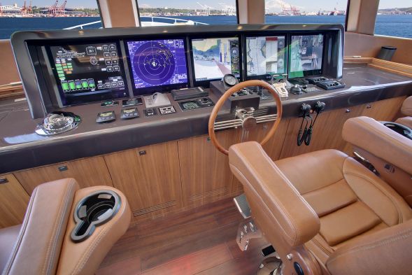
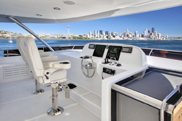
H Pilot House:
- 1 Floors: Teak – varnish
- 2 Cabinet/joiner work: Varnished teak
- 3 Counter tops and instrument panel faces: Formica #939 dark gray
- 4 Teak table at settee to slide in and out.
- 5 Settee with chart drawers under
- 6 Helm seat – Stidds 500N-2X2 Low Back “Slimline”. Ultra-Leather and pedestal color are buyer’s choice
- 7 Chart table w/Cantalupi “Rico” chart light
- 8 Locker interior finish: Formica
- 9 Book shelves and chart drawers as located per interior drawings
- 10 Top of instrument console to be wrapped in black leather or ultra leather
I Forepeak (Chain Locker) Water tight collision bulkhead:
- 1 Shelves: Longitudinal plywood shelves with 5″ fiddles provided port and starboard for storage
- 2 Pad eye in each locker for bitter end of chain
- 3 Finish: Painted with gray gel coat
- 4 Locker to be divided for dual anchors and chain
- 5 Both lockers to be self draining thru thru-hulls at boot top.
J Captain/Crew cabins:
- 1 Floors: Carpet with pad
- 2 Cabinetry and joiner work: Formica with teak trim
- 3 Mirrors as shown on interior drawings
- 4 Hanging lockers with Cedar wood lining
- 5 Book shelves and lockers outboard of lower berth
- 6 Drawers under berths
- 7 Mattresses: Custom 5″ thick foam
- 8 Aft stairway to crew cabins and engine room
- 9 Bulkheads to be finished: Varnished teak
- 10 Washer/Dryer Combination
- 11 Forced air ventilation system with adjustable blower
K Crew head:
- 1 Floors: Lonseal #154 Sandstone
- 2 Cabinetry: Formica with teak trim
- 3 Shower to be molded FRP
- 4 Counter tops: Granite with bull nosed edges
- 5 Aluminum/glass bi-fold shower door
- 6 Towel bars TBD
- 7 Toilet paper holder TBD
- 8 Full height mirror over sink
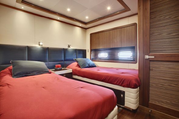
L Forward port and starboard guest cabins:
- 1 Floors: Carpet with 2 lb./sq. ft. 1/2″ thick Soundown under lament pad
- 2 Cabinet/paneling: Varnished teak
- 3 Hanging locker interior finish: Cedar wood
- 4 Dresser outboard
- 5 Drawers under bunk
- 6 Mattresses: Custom 5″ thick foam
- 7 Night stands next to bunk
- 8 Teak headboard frame
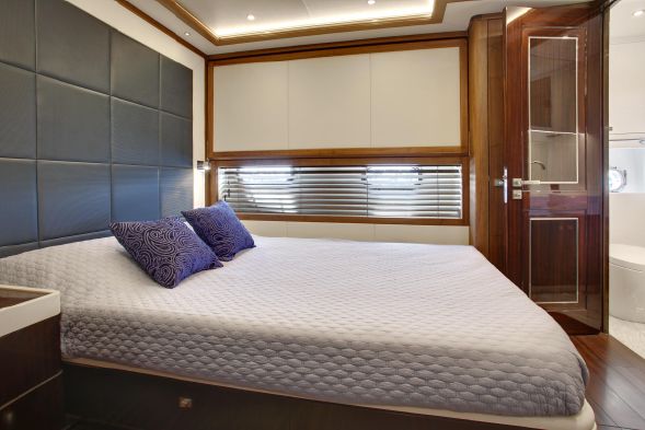
M Forward VIP cabin:
- 1 Floors: Carpet with 2 lb./sq. ft. 1/2″ thick Soundown under lament pad
- 2 Cabinet/paneling: Varnished teak
- 3 Mirrors as shown
- 4 Hanging locker with Cedar wood lining
- 5 Drawers under berths
- 6 Mattresses: Custom 5″ thick foam x 2
- 7 Forced air ventilation system with adjustable blower
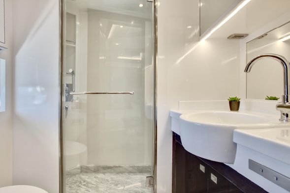
N Port and starboard and VIP guest heads:
- 1 Floors: Ceramic or stone tile to be specified with order
- 2 Cabinetry: Varnished teak
- 3 Shower to be molded FRP
- 4 Counter tops: Granite with bull nosed edges
- 5 Aluminum/glass bi-fold shower door
- 6 Towel bars
- 7 Toilet paper holder
- 8 Full height mirror over sink
Accommodation
11 LIGHTING (Per lighting plans)
A Main overhead lighting:
- 1 Main overhead lighting throughout interior: 230VAC Cantalupi Fixtures Per the lighting plan. Lighting controlled by wall switches.
B Exterior overhead lights:
- 1 F/B and side decks: 230VAC Cantalupi Fixtures Per the lighting plan.
C Overhead reading lights:
- 1 Cantalupi Fixtures Per the lighting plan.
D Engine Room and Lazarette Lights:
- 1 230VAC fluorescent
- 2 24VDC as emergency lighting
E Courtesy Lights:
- 1 Exterior: LED 24VDC White
- 2 Interior: LED 24VDC Red
- 3 24VDC LED white rope lighting under settees, bunks and toe space in selected areas interior and exterior, white exterior and red interior.
- 4 Hanging Locker Lights and misc. Lockers: LED 24VDC
Accommodation
11 LIGHTING (Per lighting plans)
F Navigation lights:
- 1 Port nav light – Aqua Signal 55 Series:#55300 24VDC
- 2 Star nav light – Aqua Signal 55 Series:#55200 24VDC
- 3 Stern light – Aqua Signal 55 Series:#55500 24VDC
- 4 Steaming light – Aqua Signal 55 Series:#55400 24VDC
- 5 Anchor light – Aqua Signal 55 Series:#55000 24VDC
G Owner’s cabin and port and starboard guest cabins reading fixtures:
- 1 Owner’s cabin and port and starboard guest cabins to have one or two 24VDC Cantalupi “Vienna” chrome bronze swing arm reading lights (4 total)
H Wall Lamps in salon/Dining:
- 1 In three (3) locations in Salon
- 2 In two (2) locations in Dining Area
I Accent lights in heads:
- 1 Four (4) owner’s head, Two (2) day head, Three (3) total for guest heads.
J Deck Floodlights:
- 1 Three (3) Aqua signal 230VAC/500 watt series 1069 mounted on port and starboard F/B hardtop and one facing aft on the mast.
K Search Light:
- 1 Carlisle & Finch 200 watt spotlight #XY2EDE-RF with dual station remote controls. Unit mounted on the flybridge hardtop.
OnDeck
- 12 EXTERIOR, DECK HARDWARE, and EQUIPMENT
- A Deck and Hardware:
- 1 All horizontal surfaces on deck to have a diamond pattern non skid as shown in deck plan -standard non skid to be a contrasting color to parameter deck
- 2 Stainless 316 handrails 2″OD with electro polished bases. All rails shown on drawings to be standard in addition to those specified
- 3 Handrails at transom
- 4 Hand rail around aft deck coaming 2″ dia.
- 5 Handrail on underside of aft deck overhang 1 1/2″ O.D.
- 6 Hand rail at port and starboard side boarding doors
- 7 Recessed hand rails from lower deck to P/B deck
- 8 S/S 316 Hawse fittings with rollers:
- 9 S/S 316 18″ bollards per drawing
- 10 Upper rub rail cap to be 316 stainless steel 1/4″ thick fastened with flush 316 stainless steel fasteners. Stainless steel caps on upper and lower rub rails as shown in design.
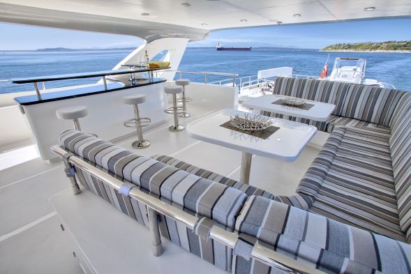
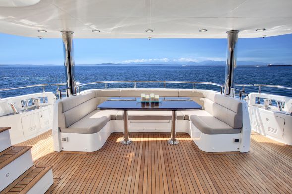
- 11 Settee, molded fiberglass with cushions at foredeck and aft deck
- 12 Manship ports in hull and deck as shown on design. Ports positioned as follows:
- 13 All opening ports to be fitted with screens and deadlights
- 14 Fixed window in day head
- 15 Stainless steel 2″ dia. 316 rails and stanchions on upper deck and F/B deck . Rails to have welded on round bases with fastening studs on bottom and dual 1 1/2″ divider rails as shown on drawing.
- 16 Foredeck to have 316 elliptical stainless rail with 2″ diameter stanchions. Welded to round bases with fastening stud welded on bottom.
- B Anchor Storage:
- 1 Stainless steel 316 anchor pockets port and starboard.
- C Windshield Wipers:
- 1 “Exalto” two (2) speed self-parking motor, with wash system for three (3) front windows
- 2 #EX2167.32 wiper motor 223BS 24VDC/23Nm, for (1- 3/8” {9.5mm} ) bulkheads
- 3 #EX2135 T1 Pantograph arm 17.7″-23.6″ (450-600mm) adjustable
- 4 #EX2174 curved wiper blade 17.7″ (450mm)
- 5 #EX2159 Combo switch for single wiper 24VDC
- 6 #EX2143 24VDC solenoid valve for wash system
- 7 #EX2136.03 tubing retainer strip
- 8 #EX2184 Washing Jet for type 1 adjustable pantograph arm
- 9 #EX2186 plastic bulkhead connector for 19.7″ (500mm) (new style)
- 10 #EX2154 Tubing ¼” (6.35mm) soft black x 5 meters
- 11 #EX2157 Tubing ¼” (6.35mm) hard black for push fit plumbing fittings x 5 meters
- 12 #EX2129 elbow 6x.24″ (6mm)
- 13 #EX2166 T-coupling 6x6x6mm
- 14 #EX2119 straight coupling , ¼” (6.35mm)
- 15 #EX2105.025 Gallery with adjustable spring to tension wiper against window
- D Horn:
- 1 Kahlenberg dual trumpet #D-1 with chrome finish and fog timer 230VAC compressor w/24VDC solenoid
- E Deck hatches:
- 1 Per deck plan, Lewmar #70 “Ocean Series” to include insect and privacy screens. One (1) Lewmar #60 “Ocean Series” to include insect and privacy screens.
- 2 Install (1) Lewmar #70 “Ocean Series” on the port side of the lower platform to access the flybridge hardtop.
- F Windows:
- 1 10-12mm” thick tempered glass
- 2 All side windows to be tinted glass
- 3 All salon and pilothouse windows are recessed 1″.
- 4 All salon windows to have storm plate receptacles
- G Aluminum doors:
- 1 Pacific Coast Marine as follows (Note: interior as well as exterior PCM doors are included in this schedule):
- 2 Pilothouse–2ea, Water Tight Dutch door, one L.H. Mortise hinge, one R.H. Mortise hinge. C.O. 21″ x 73″
- 3 Salon after–1ea, Water Tight double opening door with all glass panels.
- 4 Salon port side, Water Tight door, one RH Mortise hinge
- 5 Engine room–1ea, Water Tight model no. PCM4170-W with sound blanket core, painted. L.H. surface mount hinge. C.O. 21″ x 73″.
OnDeck
12 EXTERIOR, DECK HARDWARE, and EQUIPMENT
H Boarding doors:
- 1 Port and starboard – opening in two pieces. Top to fold up and over and bottom to open outboard. Stern doors on port and starboard side aft per drawing. Doors to have “blind” dog lock/handles.
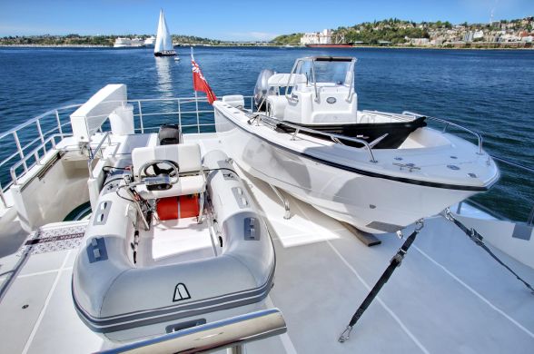
I Davit:
- 1 2200 LB capacity hydraulic/240VAC davit with extendable boom to 20 feet mounted per drawing.
J Bottom treatment:
- 1 Five (5) layers of epoxy barrier coat and three (3) coats of anti fouling paint
K Deck Drains:
- 1 Bridge deck and Fly Bridge deck to drain through (8) 2″ deck drains (4) per side.
- 2 Lower side decks to drain through freeing ports.
L Control stations:
- 1 Port and starboard side of forward bridge deck equipped with helm controls, bow and stern thruster controls, start/stop/horn.
- 2 Aft deck control station equipped with helm controls, bow and stern thruster controls, start/stop/horn.
M FRP hardtop over F/B:
- 1 FRP hardtop over F/B with molded in non-skid 4″dia. Stainless steel support stanchions at forward end, port and starboard
N Stern capstan winches:
- 1 Two (2) Maxwell VC 2200 port and starboard cockpit
O Flag Staff:
- 1 60″ teak flag staff with 2″ socket for aft P/B deck rail.
P Anchor:
- 1 300 lb. stainless steel
Q Anchor Chain:
- 1 400 ft. 5/8″ (16mm) Stud Link chain
R Swim ladder:
- 1 Stainless steel with teak steps mounted on swim step under FRP hatch accessible from water
S Tender Docking:
- 1 Two (2) fold up style 10″ cleats on swim step port and starboard for dinghy tie up
T Anchor Windlass and Fittings:
- 1 Dual matched set of Maxwell VWC 4500 hydraulic three (3) station controls pilothouse, fly bridge, aft deck and foot switches with chain counters and band brake and 5/8″ (16mm) Stud Link chain gypsy x 2
- 2 Chain stoppers with devils claw chain tensioner for 1/2″ diameter Stud Link chain
U Exterior locker doors
- 1 All exterior locker doors to use flush stainless steel pull rings for latches
- 2 All exterior locker doors to have louvered stainless steel vents
V Life raft pads
- 1 Port and starboard side of F/B deck
W Swim Platform
- 1 Three (3) 21/2” diameter “u” shaped rails across swim step
X Foredeck lockers
- 1 2 flush style port and stbd as shown on drawings. Hinges to be Freeman Style “Large Yoke”
Y Deck Locker Misc.
- All deck lockers and stowage boxes to be fitted with stainless steel gas shocks of the proper rating
Z Teak Deck
- 1 Teak deck on swim platform, cockpit and side deck, Portoguese bridge, foredeck
Inventory
Standard Equipment
- 1st Onan 40kw generator
- 2nd Onan 22.5kw generator
- Aqualloy 22 propeller shafts
- Amartech shaft seal system
- ABT hydraulic bow and stern thusters
- ABT TRAC #370 digital stabiliser system with 20sq. ft. fins and dual station controls
- Kobelt hydraulic steering system
- Steelhead 2200lb davit
- Maxwell VWC hydraulic windlass
- 2 Maxwell VC 2200 capstans at port and starboard cockpit
- ESI fuel polishing system
- Reverso oil change pump
- BEP electrical main breaker panels
- Seafire fixed fire extinguishing system
- Tecma freshwater toilets
- Cruisair air conditioning system
- Liebherr or equivalent home size large refrigerator in the galley
- Raritan or equivalent ice maker
- Siemens or equivalent microwave
- Siemens or equivalent electric or propane stove
- Siemens or equivalent dishwasher
- Broan or equivalent trash compactor
Optional Extras
- Options
- Awlgrip PU painted hull colour
- Davit upgrade to 3500lbs
- Kabola bathroom heating system
- Under water lighting
- Sky roof on hard top
- Teak deck on F/B helm station and dinghy deck
- Teak coaming on rail for foredeck, aft deck and flybridge
- Illuminated boat nameplate
- Helm navigation, Communications and entertainment package
- Ships monitoring system for all vital systems onboard
- Opacmare passerelle
- Opacmare swim plaform